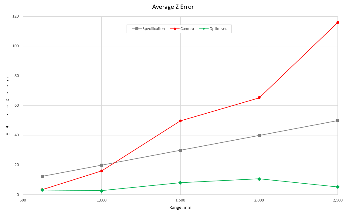
Intel’s RealSense cameras are astonishingly precise but not as accurate. By optimising the calibration of the depth stream and correcting for non-linearity, the accuracy can be improved by an order of magnitude at 2.5 metres and becomes almost linear in the depth:
Sources of error
Calculating the coordinates of the 3D point corresponding to a depth reading is straightforward trigonometry – here‘s a quick refresher – but the accuracy of the results depends on several factors.
Accuracy of the intrinsics
The supplied Intel® RealSense™ Depth Module D400 Series Custom Calibration program uses the traditional method, displaying a chequerboard to the camera in various poses and solving for the intrinsics. There are several issues with this methodology:
- This method establishes the intrinsics solely for the colour camera.
- Although it resolves to sub-pixel accuracy, it does so on a single frame, which is imprecise. The results of 3D calculations are extremely sensitive to errors in the field-of-view: A one-degree error in the vertical field of view translates into >11mm error at 1 metre. Concomitant errors in the horizontal field of view make matters worse and they are quadratic in the depth.
- The depth stream is synthesised by the stereo depth module and the vision processor. Imperfections anywhere in the chain (unforeseen distortion, varying refraction at different wavelengths, heuristics in the algorithms, depth filtering) may negatively affect the accuracy. One cannot assume that an apparently perfect colour image will produce ideal results in the depth map.
Non-linearity
This is readily observed with the supplied DepthQuality tool. When viewing a target at a measured distance of 1’000 from the glass, the instantaneous reported depth is out by ~22mm:
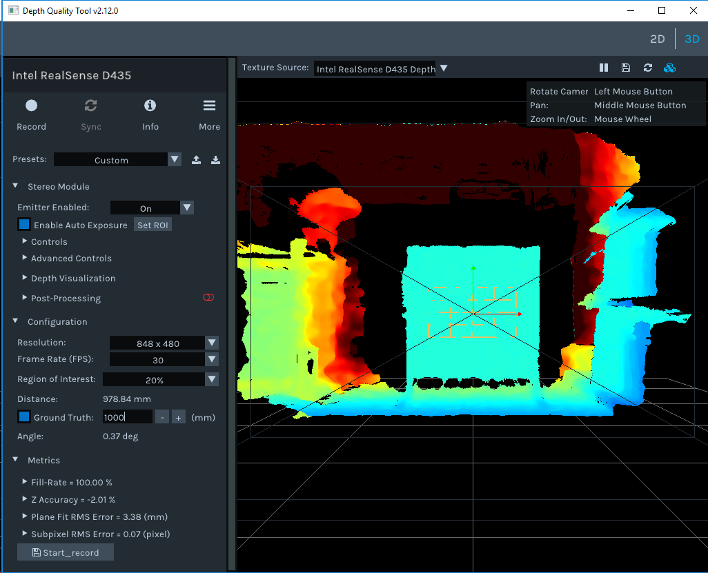
By averaging depth measurements over a period, errors in precision can be eliminated. Averaged over 1’000’000 measurements, my out-of-the-box D435 reports a range of 980.70mm – an error of 19.3mm. This is within the specified accuracy 2%=20mm but increases quadratically, as is to be expected. Fortunately, this non-linearity appears to be constant for a given camera and once determined, can be eliminated.
Focal Point
The focal point of the depth map is supplied in the Intel RealSense D400 Series Datasheet, for a D435 it is defined as being 3.2mm behind of the glass. Presumably due to the manufacturing tolerances of ±3%, the focal point may in reality be tens of mm away.
Mounting
No matter how precisely the camera is mounted, there will be errors between the mounting and the camera’s true central axis. Knowing them improves the accuracy when translating from the camera frame to the parent (vehicle or world) frame.
Solution
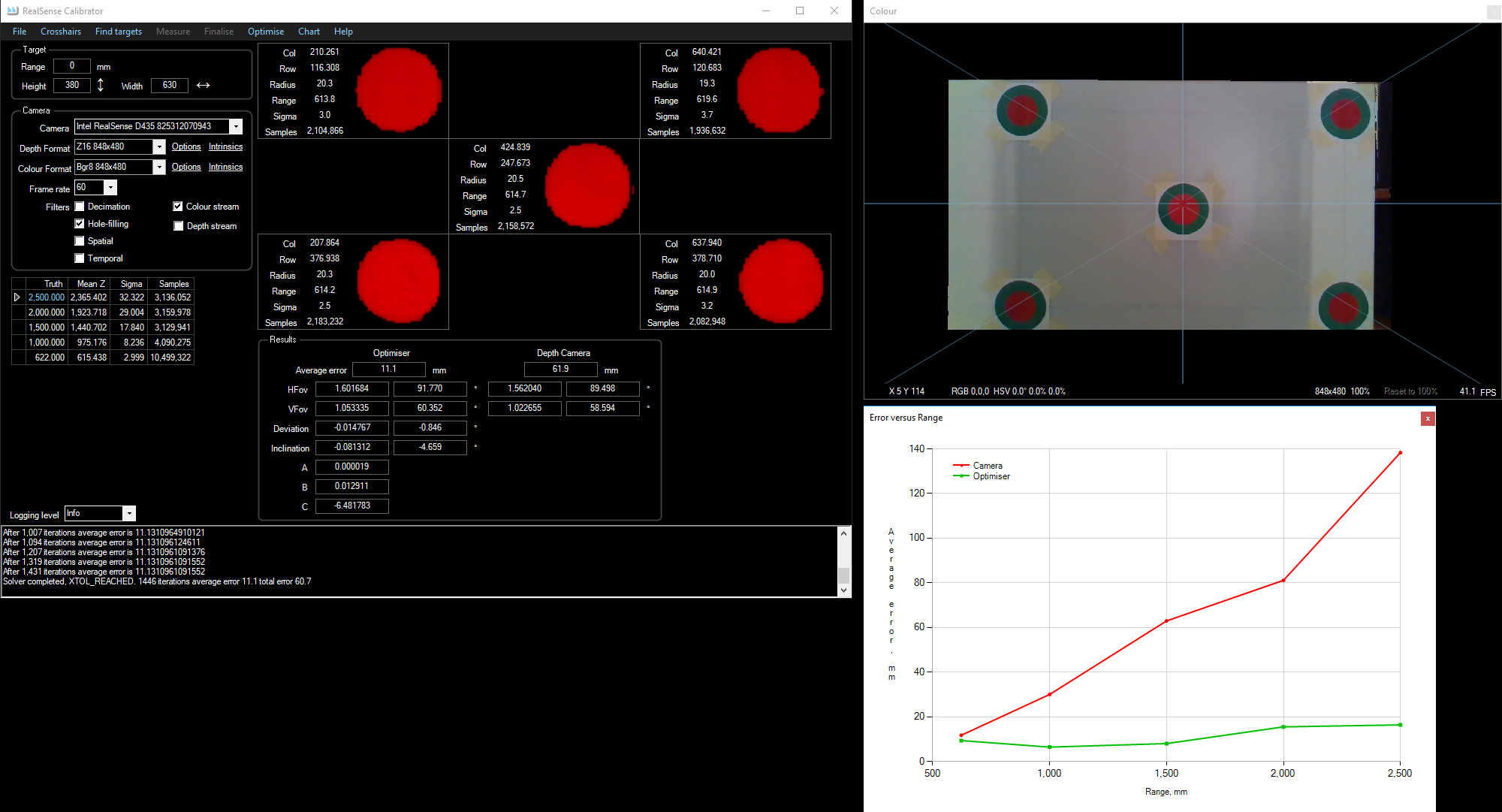
I have written a program that calibrates a camera based solely on measurements in the depth stream. It derives all the parameters discussed above by making several observations of a target with known dimensions. A much higher degree of accuracy is obtained by averaging over a large number of measurements. The optimal parameter values are then calculated, as a single problem, with a non-linear solver.
It is open-source, available on GitHub https://github.com/smirkingman/RealSense-Calibrator
Screenshot of an optimiser output:
Discussion
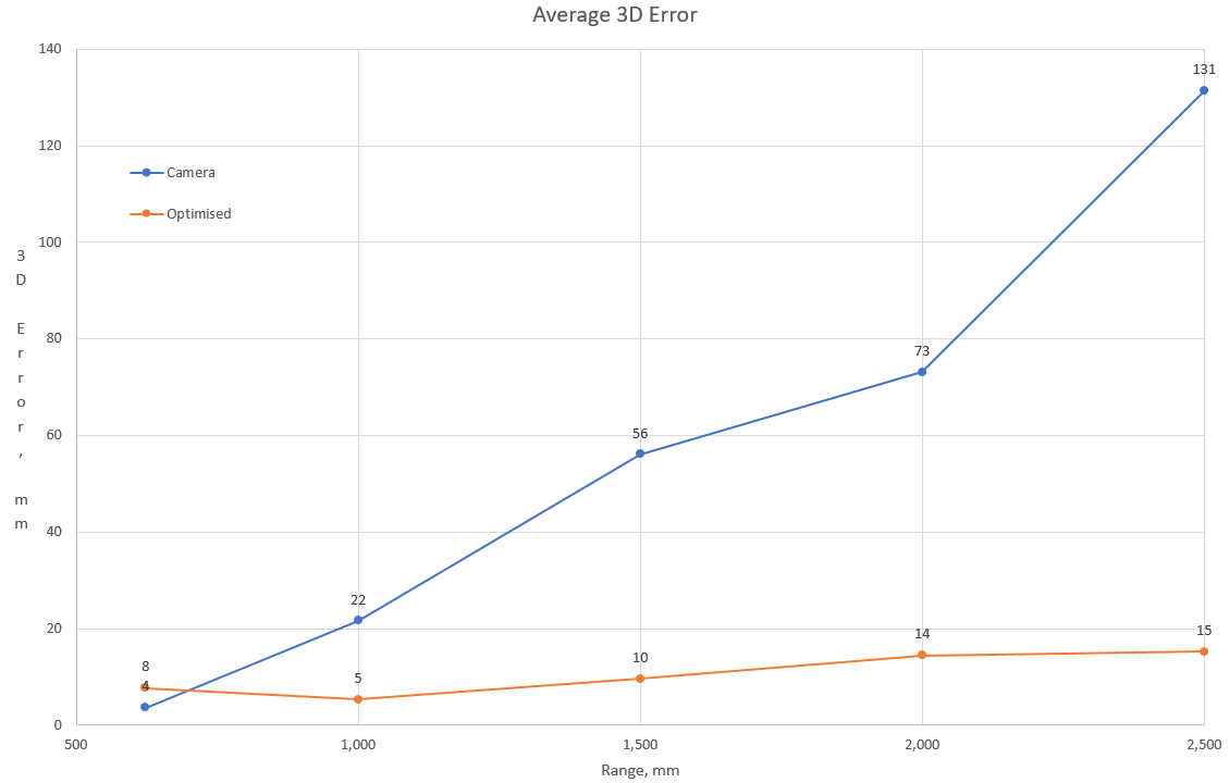
The comparisons presented above use the Z-range as the metric, as this is the metric in the reference documentation. The Z measure alone is only part of the answer, a more realistic metric is the 3D error of the point: the vector between the truth and the 3D point determined by the camera and software. Futhermore, just supplying a number doesn’t tell the whole story. Traditional error analysis supplies descriptive statistics, which give a value and a confidence known as the 68–95–99.7 rule, which allows us to make statements like “The error will be no more than Xmm 99.7% of the time” (3-sigma, or 3σ).
The 3D error – the length of the vector between the true coordinates of the point and what the camera+software reported is:
The 3-sigma error is:
what this shows is that at 1.5 metres, the coordinates of the 3D point will be between 1’447 and 1’553 from the camera 99.7% of the time.
![\[1000*tan(56/2)=531.7mm\]](http://www.calvert.ch/maurice/wp-content/ql-cache/quicklatex.com-ef77efcfe19702eb7e6c64b199c4dd6e_l3.png "Rendered by QuickLaTeX.com")
![\[((480-1)/2)+(-398.5)/531.7*((480-1)/2)=row\ 60\]](http://www.calvert.ch/maurice/wp-content/ql-cache/quicklatex.com-e3df723ae96bbcf7abaf5ddb2605087a_l3.png "Rendered by QuickLaTeX.com")
![\[Atan(398.5/1000)=-21.7^\circ\]](http://www.calvert.ch/maurice/wp-content/ql-cache/quicklatex.com-114ed79cd069c6d25838d630a076f402_l3.png "Rendered by QuickLaTeX.com")
![\[VFov2=VFov/2\]](http://www.calvert.ch/maurice/wp-content/ql-cache/quicklatex.com-be0fff1d91820dda496838fbd33eda6f_l3.png "Rendered by QuickLaTeX.com")
![\[VSize=Tan(VFov2)*2\]](http://www.calvert.ch/maurice/wp-content/ql-cache/quicklatex.com-eb42f116c7fec982c4a1ef95ba5e8d1a_l3.png "Rendered by QuickLaTeX.com")
![\[VCentre=(Rows-1)/2\]](http://www.calvert.ch/maurice/wp-content/ql-cache/quicklatex.com-95f0da83bf6eb62ad3ecae78db032f98_l3.png "Rendered by QuickLaTeX.com")
![\[VPixel=VSize/(Rows-1)\]](http://www.calvert.ch/maurice/wp-content/ql-cache/quicklatex.com-09ae8167b05622d7f07ef162aee1b4ad_l3.png "Rendered by QuickLaTeX.com")
![\[VRatio=(VCentre-row)*VPixel\]](http://www.calvert.ch/maurice/wp-content/ql-cache/quicklatex.com-29c4a3f95bf599ee89a18d86f05e7c72_l3.png "Rendered by QuickLaTeX.com")
![\[Y=Range*-VRatio\]](http://www.calvert.ch/maurice/wp-content/ql-cache/quicklatex.com-bafa5fbfeb7018f3b346040d36f3c4eb_l3.png "Rendered by QuickLaTeX.com")
![\[VFov2=56/2=28\]](http://www.calvert.ch/maurice/wp-content/ql-cache/quicklatex.com-df5af8854955795a66e97d92340c1ac9_l3.png "Rendered by QuickLaTeX.com")
![\[VSize=Tan(28)*2=1.0634\]](http://www.calvert.ch/maurice/wp-content/ql-cache/quicklatex.com-10d5441912c0fc84ce0907d0c001c39c_l3.png "Rendered by QuickLaTeX.com")
![\[VCentre=(480-1)/2=239.5\]](http://www.calvert.ch/maurice/wp-content/ql-cache/quicklatex.com-ade6ec1c12a1adbdb10cd6a19aca58a6_l3.png "Rendered by QuickLaTeX.com")
![\[VPixel=1.0634/(480-1)=0.00222\]](http://www.calvert.ch/maurice/wp-content/ql-cache/quicklatex.com-e509fd7c99ac59d20affb6128ef363b7_l3.png "Rendered by QuickLaTeX.com")
![\[VRatio=(239.5-60)*0.00222=0.3985\]](http://www.calvert.ch/maurice/wp-content/ql-cache/quicklatex.com-7ed2ca98b44d07afbfad90728073e301_l3.png "Rendered by QuickLaTeX.com")
![\[Y=1000*-VRatio=-398.5 mm\]](http://www.calvert.ch/maurice/wp-content/ql-cache/quicklatex.com-dc173670b9f1a02d2a42e9742654b9fd_l3.png "Rendered by QuickLaTeX.com")